


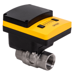

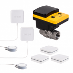

Detailed installation steps with valve and alarm panel
1. Purpose
The purpose is to create a two-way connection between the Sedna system and the alarm panel in order to monitor and/or notify the status of the Sedna system, for example to send an alert to a third party such as a central alarm station.
2. Scenarios
There are 2 main scenarios possible:
2.1) Notify the alarm system/central when a water leak is detected. In fact, the Sedna system will send the leak detection notification to the alarm panel through the multi-controller and then to the alarm central.
2.2) Monitor the water valve with the alarm system (close or open the valve depending on the arming/disarming of the alarm system).
2.3) It is also possible to monitor the valve independently of the arming/disarming of the alarm system.
3. Requirements
3.1) Power source
Setting the power source for the MC3100ZB is critical (power mode). Ideally, the power should be taken directly from the panel (auxiliary output), because in the event of a power failure, the multi-controller will remain functional via the panel’s battery (secondary power supply) – in this case, the batteries in the MC3100ZB are no longer needed.
* It is important to check the panel for the availability of terminal block space for power and battery capacity.
3.2) Sedna alert to the alarm panel
You must have a free zone (ZONE X) in the alarm panel for the connection of the cable coming from the MC3100ZB (OUT1).
3.3) Control of the valve from the alarm panel
You must have a relay output (dry contact) available in the alarm panel for the connection of the MC3100ZB (IN1) cable, or a PGM (programmable) output that controls a relay card.
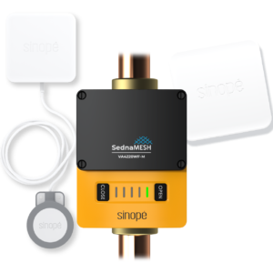
4) Installation
4.1) Installation location
It is best to install the MC3100ZB outside the alarm panel or a secondary panel. This will avoid problems with signal loss due to interference, as most panels are made of metal and some of the panel modules have an RF antenna.


4.2) Power supply
The alarm panel’s power supply is in this case the main power source and its battery the backup source. Therefore, simply select Supply in the MC3100ZB.
Power the MC3100ZB by connecting a cable from the AUX or POWER AUX output of the alarm panel (+ and -) to the POWER terminal block of the MC3100ZB (no polarity).
**WARNING: The panel’s AC power supply and its battery or other power source must be disconnected before any manipulation.**
4.3) Sending an alert after a water leak
Connect the OUT1 output of the MC3100ZB to the selected Zone of the alarm panel and program it in advance. Programming the water zone as a monitored zone is recommended in order to notify the control panel.
It is recommended to locate the end of line resistor (security monitoring) in the alarm panel rather than in the MC3100ZB.


4.4) Monitoring the valve from the panel (arming the system)
Connect the relay output of the selected alarm panel (N/O) and pre-program it into input 1 (IN1) of the MC3100ZB. Programming the relay (contact closure) when the system is armed is required.
4.5) Control the valve from the panel at any time (Either from the panel app, a button or after arming the system)
Connect a relay card to a PGM output, connect the selected relay output (dry contact – N/O) and program it in advance to input 1 (IN1) of the MC3100ZB.
This function also allows you to program the closing of the water valve according to a time slot (applications in several sectors) or even a timer.
Normally, the PGM is OFF, and when the system is armed, the PGM activates the relay card (ON) and closes the valve (N/O contact output to IN1 input of the MC3100ZB). That’s why if the system is disarmed, its state is OFF.
*This function depends on the alarm panel hardware and software.


5) Programming
5.1) Manually connect the MC3100ZB to the valve (pair as a sensor – button B on the valve).
The factory programming of the MC3100ZB as a secondary valve device activates only the OUT1 output and the IN1 input. At this time, there are no functions for OUT2, IN2, temp, HR, sensor temp.
*It is possible to add options such as having a water overconsumption alert (flow sensor). For example, after a continuous consumption of 1.5 hours, you should not close the valve, but rather activate the OUT2 output of the MC3100ZB (connected to a zone of the alarm panel). The valve will not be closed, but the central unit will be able to contact the customer to know if everything is under control (no Sinopé alert = less pings/sms for our servers).
6) Notes
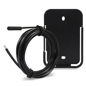
Identification of the cables (to the panels and to the MC3100ZB) is strongly recommended (see photo – Identification 1). It allows easy access and understanding of the installation for everyone. For example, during a service call, any technician or company can intervene.