Proceed as follows to install your water heater controller
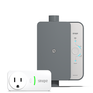
Install your smart water heater controller
Proceed as follows to install your water heater controller
Installing your smart water heater controller
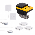
Make sure you have all the items that are included in the box
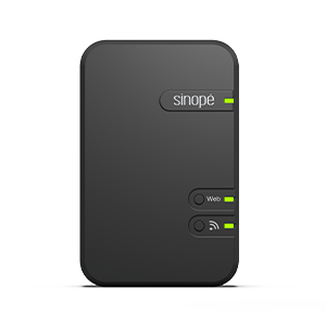
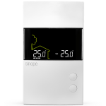
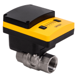
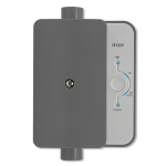
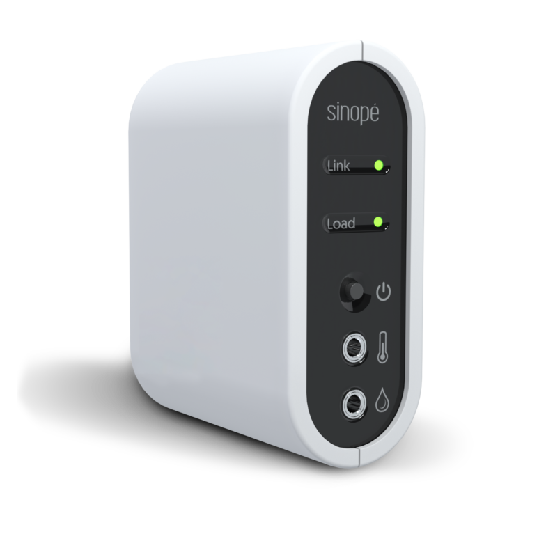
1 Zigbee water heater controller
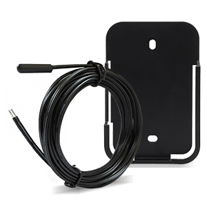
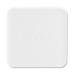
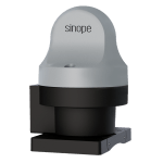
1 AC3500-01 temperature sensor
1 1/2″ steel lock nut, NPSM threaded
3 connectors
Installation guide – French version
Installation guide – English version
Follow the installation steps
Here is a detailed step-by-step guide that will take you through the installation of your smart water heater controller.
The installation of this controller must be made by a certified electrician and must be installed in conformity with the national and local Electrical Codes.
The electrical load controller is designed for indoor use only.
1
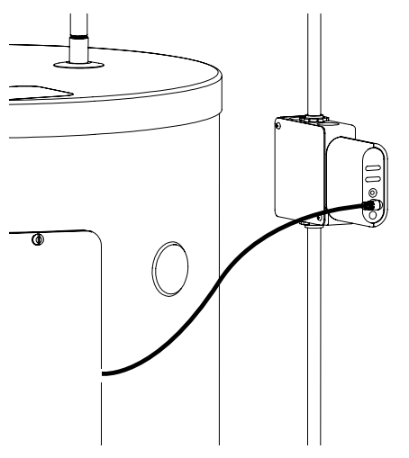
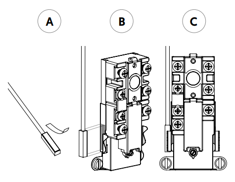
A) Materials required for installation when the power supply is located on the side:
Make sure to turn off the circuit from the electrical panel to avoid any risk of electric shock.
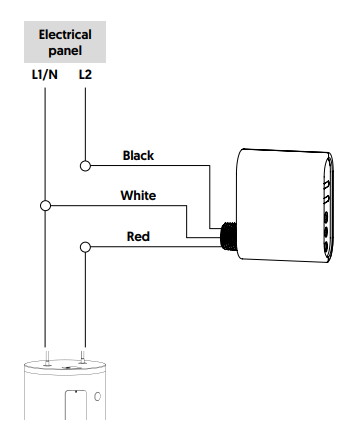
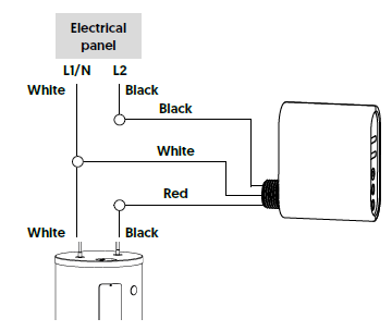
Installation on a 240V circuit
Installation on a 120V circuit
3
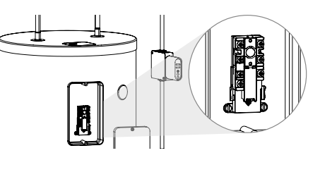
Insert the water heater wire (load) and the power wire (line) into the electrical box and secure them with wire clamps.
Install an electrical box ground wire to the water heater ground screw.
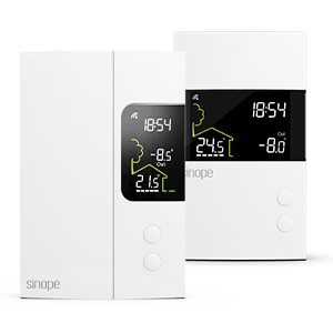
Installation of the temperature sensor
Here are the steps to install the AC3500-01 temperature sensor from your Calypso controller on your water heater.
How the protection mechanism works As a protective measure, the controller is designed to restart the water heater if the water temperature drops below 45°C (113°F) , even if the controller is not connected to a gateway.
If the temperature sensor is not installed, the protection will no longer apply and the water heater can then remain off for a longer period. It is possible to deactivate the protection in the Neviweb app.
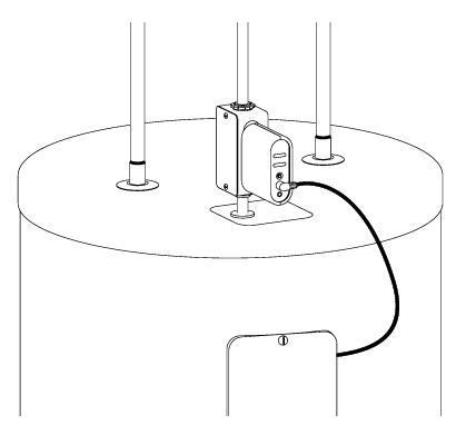
1
Unscrew and remove the door plate located at the top of the water heater.
2
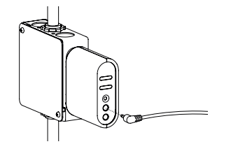
Plug the probe into the controller’s temperature port.
3
Remove the sticker liner from the end of the probe and affix it to either side of the water heater’s thermostat, as illustrated. Screw the water heater door plate in place.
Note: Clean the side of the thermostat with isopropyl alcohol before affixing the probe.
4
Make sure to adjust the water heater’s temperature between 55°C (131°F) and 60°C (140°F) to use the controller during your power utility’s peak management events.
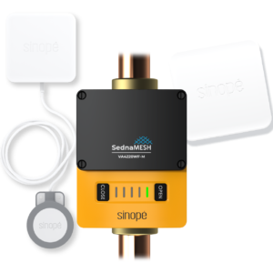
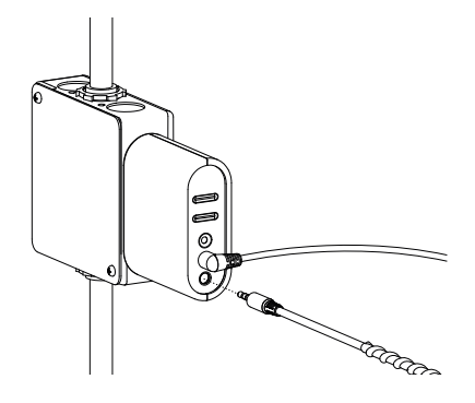
Installation of the AC4200C-02 water detection cable
Here is a detailed step-by-step guide that will take you through the installation of the water detection cable AC4200C-02 (available in option) into the water heater controller. The water heater can therefore shut off its power as soon as a leak is detected.
1
Plug the water detection cable into the controller’s lower port.
2
Position the water detection cable at the base of the water heater and secure its position with the provided fasteners.