
To make the 3-way connection of your switch or dimmer, refer to the wiring diagram provided in your product’s installation manual.
The installation manual and a document containing the 3-way connection diagrams are also available for download in the Documentation section of your lighting product.
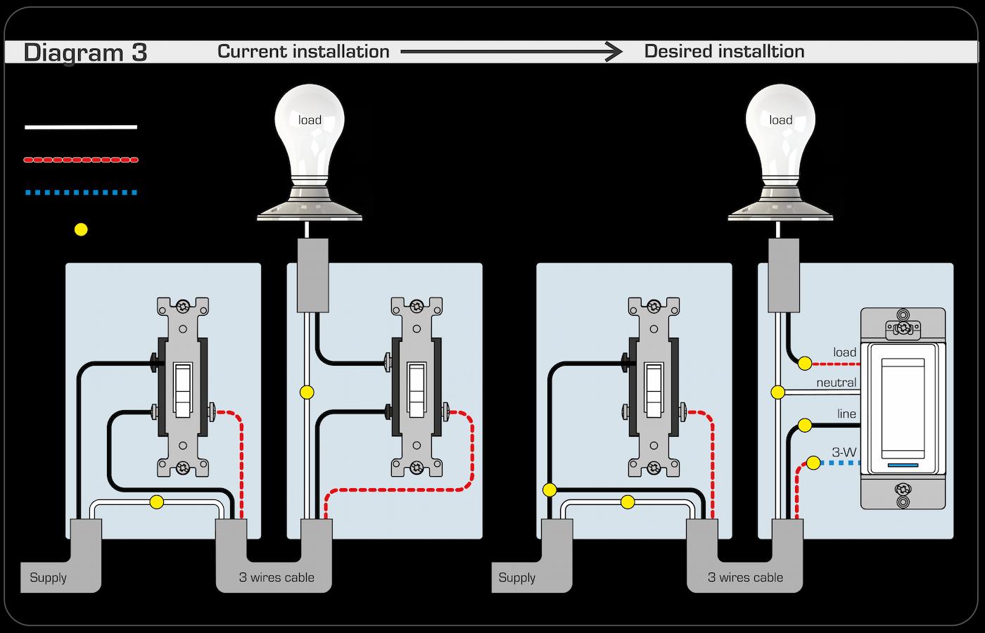
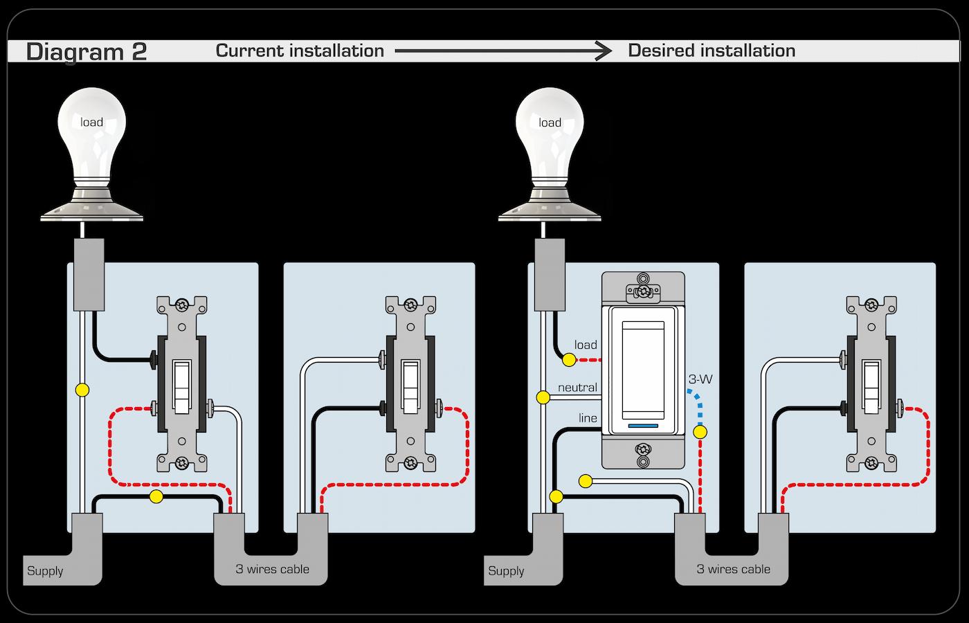
Scheme selection
Before proceeding with the installation, identify:
- the point where the power cord arrives
- the point where the charging wire originates
Next, select the diagram that best matches your installation from the options provided.
Next, refer to the installation guide to learn how to connect your switch or dimmer to your compatible gateway.
Virtual 3-way connection of your switch or dimmer
It is also possible to create a virtual 3-way branch by configuring automations in Neviweb.
In this case, the switch or dimmer acts as a trigger for the automations.
Automations to configure
To replicate a 3-way operation, create the following 4 automations:
- When I activate switch 1 → activate switch 2
- When I disable switch 1 → disable switch 2
- When I activate switch 2 → activate switch 1
- When I disable switch 2 → disable switch 1
Product models associated with this article:
- (Zigbee) SW2500ZB, DM2500ZB, DM2550ZB
- (Mi-Wi) SW2500RF, DM2500RF